Blog article
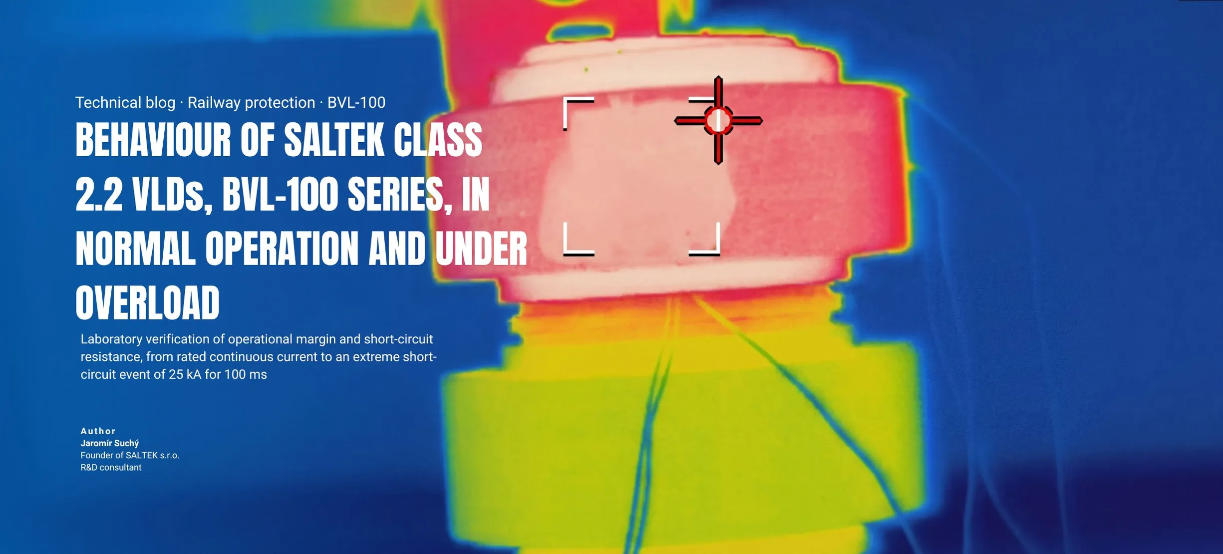
BEHAVIOUR OF SALTEK CLASS 2.2 VLDs, BVL-100 SERIES, IN NORMAL OPERATION AND UNDER OVERLOAD
-
 Jaromír Suchý Author of the article
 -
06. 05. 2026
Blog article
Overview
This article summarises how SALTEK BVL-100 voltage limiting devices behave under continuous current loading, under real field conditions and during extreme short-circuit overload. The goal is to show not only compliance with the relevant standards, but also the practical operating reserve of the device.
Continuous current
Overload reserve
Short-time withstand
Extreme overload
Function And Principle
SALTEK Class 2.2 voltage limiting devices (VLDs) are installed in railway stations between the protected equipment, or protective earth, and the return circuit. Their primary role is to provide equipotential bonding and limit touch voltage to a safe level, helping protect personnel, passengers, and assistance animals.
In the specific VLD-O mode, operation does not require tripping of section switches. SALTEK BVL devices can also fulfil the function of a VLD-O mode. If a fault causes the traction line to contact an exposed conductive part, the unit creates an intentional short circuit, immediately disconnecting the affected section and preventing hazardous touch voltage.
Normal Operation
Contact resistance and internal losses thermally load the thyristor semiconductor chip, causing it to heat up. SALTEK BVL-100 devices therefore use robust integrated heat sinks to efficiently dissipate heat and increase permissible continuous current-carrying capacity.
The device behaviour was verified in SALTEK's laboratory using the BVL-100-120-R02 under different current levels. The measurement method was based on EN 50526-2, but unlike the standard procedure, the test did not stop after 60 minutes. It continued until the thyristor temperature fully stabilised.
The goal was to check whether the semiconductor chip would reach the 125 °C limit, above which breakdown may occur. This value is also the maximum allowable exposure temperature for the potting compound and plastic parts.
Rated test
Stabilisation
Heat sink
Thyristor

In a follow-up test at a continuous current of 150 A DC, the thyristor temperature stabilised at 114 °C and did not continue rising.
The test results confirm that SALTEK BVL-100 voltage limiting devices have a significant operational margin.
Field Measurement
Under normal service conditions, voltage limiting devices are usually exposed to currents with irregular amplitudes and different durations. Figure 2 shows a measurement record taken directly in real operating conditions.

The graph shows that, in one measured case, the current through the BVL-100 exceeded 700 A, but only for a very short duration, on the order of tens of seconds. Such events do not represent significant stress for the thyristors used in the device.
No field measurement in this dataset showed current durations of tens of minutes, which were the much more demanding conditions used in the laboratory thermal testing.
Short Circuit And Extreme Overload
EN 50526-2 and IEC 62848-2 require verification of VLD performance under short-circuit conditions. Such current can flow through the BVL-100 in the event of a contact line fault, where the device must ensure immediate tripping of the section circuit breaker.
Repeated measurements confirmed that the SALTEK BVL-100 can carry a short-time DC withstand current of 16 kA for 30 ms in recoverable mode. During that event, the device is subjected to a dissipated thermal energy, expressed as the Joule integral, of 7.7 MA²s.
Recoverable mode
Duration
Integrity test
Thermal energy
The key question was what happens after a truly extreme overload, such as a very high short-circuit current. To verify mechanical integrity under those conditions, the device was tested with 25 kA for 100 ms.

The tested BVL-100 unit withstood this extreme short-circuit current without mechanical damage. As expected, the thyristor semiconductor chip underwent breakdown and the resulting resistance was measured at less than 1 mΩ.
This outcome is desirable, safe, and fully compliant with EN 50526-2 and IEC 62848-2.
Conclusion
SALTEK VLDs in the BVL-100 series operate with a significant safety margin. Even in the case of extreme short-circuit overload, they can withstand the event without damage to the mechanical structure. That helps reduce the risk of consequential damage and fire while increasing safety in railway station environments.
Related articles
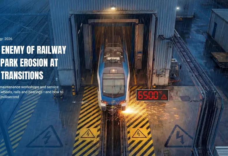
Blog • 25. 03. 2026
Why industrial sidings, maintenance workshops and service depots silently damage wheels, rails and bearings—and how to prevent it in less than 1 milli...
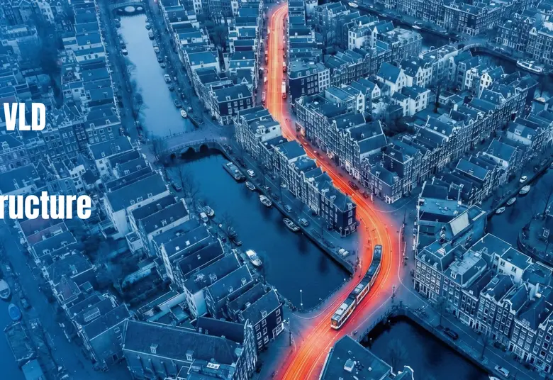
Blog • 21. 01. 2026
Modern public transit is under dual pressure: meeting strict passenger safety requirements under EN 50122-1 while protecting city infrastructure from ...
Blog • 16. 10. 2025
Expanding Our Railway Expertise – Welcome Pascal Magon to the SALTEK Team!